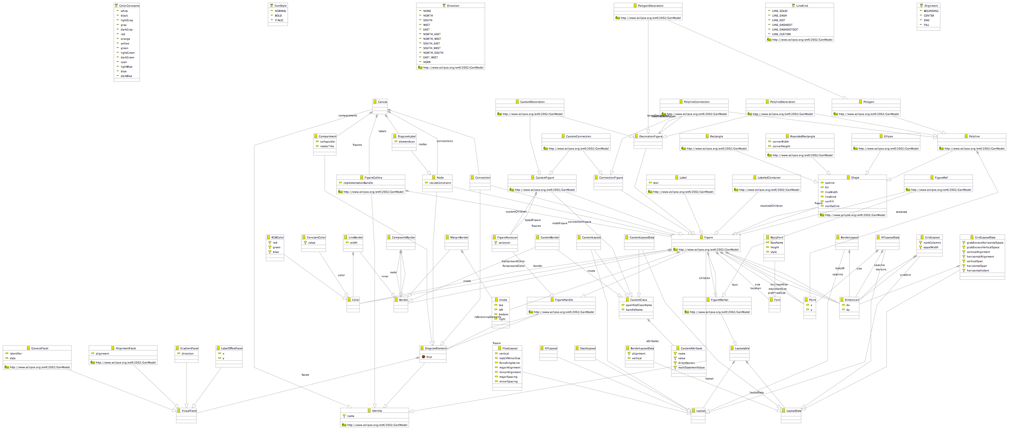
The Graphical Definition model is instantiated to gather information about the diagram editor from a toolsmith. The graphical definition model is used to describe composition of GEF figures forming diagram elements – Nodes, Connections, Compartments and Labels. Diagram element figures can be composed either from standard GEF figures or from custom figures. Every custom figure should implement the IFigure interface. Either standard GEF layouts or custom layouts can be used to arrange nested figures in accordance with attached layout data (Custom Layout Data). The information stored in this model is enough to generate the code of described composite figures. Generated figures can be instantiated later on by the diagram editor and used to visualize diagram elements. The graphical definition model can fully describe composite figure structures. If there is need to describe more behavioral aspect of generated figures, either custom figures should be used or generated code can be customized by user.
Since Graphical Definition model deals only with graphical elements and have no connections to domain-model aspects, this model can be used to generate plain GEF figures for any GEFbased applications. In other words, this model could be presented as an internal model for a GEF visual editor. Moreover, Graphical Definition meta-model was designed to describe generic graphical shapes with no dependencies on GEF so this model potentially could be used as a source of information to visualize described figures using any other diagram editor(s).
The GMF tutorials page gives fair amount of details on how-to create graphical definitions and play around with it. For more indepth details you can also look at the hints page.

No comments:
Post a Comment